© by: Boris Lutz
I replaced the capacitor C9 (27pF)
which is responsible for the speed with a smaller one (1pF).
This makes the TI
The best method to be able to change the speed is to use a
variable capacitor. You would be able to change
the speed continuously and play Assembler games at a reasonable
speed.
I accept no responsibility for this procedure and any damage that it
might cause, but if you follow my guidelines it works perfectly.
Don't use a capacitor with a capacitance below 1pF, this won't be
stable! If you are using an accelerated TI, replace the batteries
when the display contrast is at level 8 or higher! (the accelerated
version needs about 2 times the power of a regular TI-85)
The procedure described on this page is for the TI-85, the procedure
for the TI-81, TI-82, TI-83, TI-86, TI-89 and TI-92 you can find
here.
First make a backup then remove all batteries. There are three
screws which need to be removed. Two right below the battery cover
and one that holds in the backup battery. Once the screws are
removed, you have to take off the bottom part of the case.
To do this, first use the small regular screwdriver to pop the bottom
corner up. Then take the battery cover and slide it along the side of
the calculator. It will force the sides to pop open.
            Enter-Key                        F-Keys
           ________________________________________
          |
          |------>---->---->---->---->---->---->---
          |     \                             /
          |______\___________________________/_____
                  \                         /
                   \                       /
                 Open here          slide until here      (on both sides)
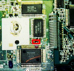
After opening the TI, you'll see a silver shield covering the TI's circuit boards. Remove the two small screws at the bottom of the shield. Once the screws are out, you'll see two circuit boards: a large one (Main board) and a smaller one for the display (Display board), C9 is on the main board.
You have to remove the display board first to get access to the capacitor (just remove the two screws and drag the display board away without damaging the wires that connect it to the main board):
NOTE:
The pictures above show the open                  |           |
TI-85 with the C9 already  re-                    |     U6    |
placed by the new 1pF capacitor.                  |           |
The old C9 is smaller                             +-----------+

This plan shows an enlargement                    C    RX
of the part of the main board                     1
around C9                        .                1
It shows the precise location                          C9
of C9:                                +-----------------------+
                                      |                       |
If you want to have a closer look     |          U4           |
at the location of C9 click here      |                       |
(thanks to George Govensky
<ViperG1@aol.com> for the
picture)
First desolder C9 from the board. Be careful: Do not overheat any part!! Do not burn the cable that connects the display board to the main board! Now you have four possibilities:
What to do |
Effect (and my comments) |
|
Put the 1pF capacitor where the old C9 used to be |
This is the easiest and most stable method, it will accelerate your TI-85 by about 3 times. |
|
Keith L. Miller [miller@cs.umt.edu] suggested to connect the 1pF cap to a switch to switch between fast and slow mode |
This is the most difficult method, but it's sometimes quite useful to switch back to normal speed especially for assembler programs. Thereby you could save some power too, since the high speed mode needs a bit more power. |
|
Another possibility is to use a variable capacitor with a range from about 1 to 30pf. |
With a variable capacitor you would be able to adjust the speed continuously and it is easier than implementing a switch. But not as fast, since most variable capacitors start at about 5pF not at 1pF |
|
[KMacTI@aol.com] suggested to just take out the capacitor (neither a bridge nor a 1pF capacitor is needed) |
This will speed up the TI about 3.5 times. This is not as stable as with a capacitor, your calculator may not work when you completely remove the capacitor. However several people reported that their calculator worked very well without any C9. |
You must have some experience in soldering, to do this!
This is the way how I do it: Take a small
screwdriver (like the one to open the calculator). Heat up one side
of C9 (not longer than one second), quickly change to the other side
and heat it up, change back and so on while you are carefully trying
to push away C9 with the screwdriver. DON'T push too hard and
DON'T heat up C9 too long! Do not burn the cable that connects the
display board to the main board!
If you push too hard you might destroy the solder pads!
However there is a way to connect the capacitor even if the pads are
destroyed but it's much more difficult.
The original capacitor is a SMD (surface mounted device) they are
rather small and more difficult to get, but you can use any 1pF
ceramic capacitor, which is small enough to fit in. If you get a
regular ceramic capacitor it should look like the picture below (not
that big, it should be about 1/6 x 1/6 inch large).
Note: It is possible that your capacitor looks different, the most
important thing is that it is labled 1pF!
To solder it directly to the board, proceed like this (see ASCII pictures below): Cut the two wires from the capacitor after about 1/4 of an inch and bend them about 1/8 of an inch away from the capacitor (but be careful not to damage the capacitor). Now you can solder the two ends to the board.
(top view)

     +---+
0----|   |
     |   |
0----|   |
     +---+

(side view)

    +---+
+---|   |
|   +---+
|
Resolder the bottom side of C9 to the top pad (where C9 was
conncted before) leaving the bottom pad open. Now, solder two about
1.5 inches long wires to your switch. It really doesn't matter which
terminals you use. Now, solder the 1pF cap to both terminals on the
switch where the wires touch.
Solder one of the wires to the top of C9 (the part of C9 that hasn't
been soldered to the board). Solder the other wire to the pad where
the bottom of C9 used to be. I found it easiest to run the wires
around U4 and then tape them down using lack electrical tape. Just
use small pieces of tape. Try not to cover any components on the
board. Especially not the connections of the backup battery!
Make sure that all your wires are as short as possible otherwise your
calculator won't be as fast as it could be. If you want, you can use
a 22pF cap instead of the old 27pF cap to minimize this effect.
   ===========
   |         |
   0--       |
\    |       |
 \  1pF      0
  \  |
   0--          <--- Location, where the old C9 used to be
   |
   ====--C9--0
       (27pF)
When the switch is closed the 1pF capacitor is bypassed (short circuited) and you have the standard speed again. If the switch is open both capacitors are connected in series and you have a capacity of 1/ ( (1/1) + (1/27) ) = 0.96pf (which is approximately 1pf)
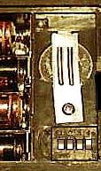
Now, the electrical stuff is done. The only thing left is to mount
the switch: Take off the back of the TI and remove all batteries. I
used a Dremal tool and cut a small rectangle out of the case just
above battery compartment #4. This leaves enough clearance for the
switch when the cover is replaced later.
Place the switch in the hole, and make sure there is plenty of room
for the switch to slide. I used a hot glue gun to secure the switch,
but just about any type of glue should work.
The last thing I did was to put black tape on the silver shield where
the switch would touch when the case is put back together. I also cut
a small square notch out of the side of the shield for the two wires
to bend up from the board to the switch.
|
|
This picture shows an implemented 4-switch DIP-switch (only one switch is used). The switch is located on the right side of the backup battery. It doesn't matter if you use a 4 DIP-switch or just one, as long as it is small enough to fit in. It just depends on what is easier to get. Many thanks to Johan Rudholm [chomma@cd.chalmers.se] who sent me this picture. |
Another possibility to adjust the speed of the TI-85 is to use a
variable capacitor with a range
starting at 5pF or lower (the lower the better) and ending at about
30pf. With a variable capacitor you would be able to adjust the speed
continuously, however it won't be as fast as with the 1pF
capacitor.
To do this you need two about 1.5 inches long wires, the variable
capacitor and an electric drill. First solder one end of each wire to
one pad where C9 used to be (after removing C9, you won't need C9
anymore) it really doesn't matter which terminals you use.
Now solder the variable capacitor to the other end of the wires. If
the variable capacitor has three connections, connection one and two
are connected together. Solder one wire to connection one or two and
the other to connection three. If your capacitor has just two
connections it doesn't matter which terminals you use.
Make sure that all your wires are as short as possible otherwise your
calculator won't be as fast as it could be. I found it easiest to run
the wires around U4 and then tape them down using lack electrical
tape. Just use small pieces of tape. Try not to cover any components
on the board. Especially not the connections of the backup
battery!
Take off the back of the TI and remove all batteries, make a hole
next to the backup battery like on the picture below, just large
enough to hold the variable capacitor.
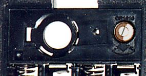
Place the variable capacitor in the hole and make sure that you
are still able to close the battery cover, maybe you have to shave it
a bit or make a hole in the cover too. I used a hot glue gun to
secure the variable capacitor, but just about any type of glue should
work. Put the glue only to the bottom of the variable capacitor on
the inner side of the case. Make sure that you don't put any glue at
the top of the variable capacitor so that you're still able to adjust
it.
The last thing I did was to put black tape on the silver shield where
the variable capacitor would touch when the case is put back
together. I also cut a small square notch out of the side of the
shield for the two wires to bend up from the board to the variable
capacitor.
The variable capacitor can be adjusted with a small screwdriver. (the
capacitance is adjusted continuously by moving the plates of the
capacitor) You have to try out which position is the fast and which
is slow. In general you can adjust the speed from 50% to 200% of the
original speed.
It is also possible to implement a software speed switch for ZShell. There are two programs that can slow down ZShell games click here to learn more about software slow down.
Note: When your calculator turns on with a few rows of black lines after you have accelerated it, you have to completely reset the calculator. Click here to see how
If you have any questions please first have a look at the SpeedUp FAQs and Trouble shooting
Boris Lutz
http://www.twistednet.ch/
You can share this plan with other TI users as long as you don't change it and include my e-mail address and home page URL.